|
DRAWMER DS501
OPERATORS MANUAL
CONTENTS:
- SAFETY
CONSIDERATIONS
INTRODUCTION
INSTALLATION
CONTROL DESCRIPTION
OPERATION
APPLICATIONS
TECHNICAL SPECIFICATIONS
SAFETY
CONSIDERATIONS
CAUTION - MAINS FUSE
TO REDUCE THE RISK OF FIRE REPLACE THE MAINS FUSE ONLY WITH THE SAME
TYPE, WHICH MUST BE A CLASS 3, 230 VOLT, TIME DELAY TYPE, RATED AT 32mA
WHERE THE MAINS INPUT VOLTAGE SWITCH IS SET TO 230 VOLTS AC. AND 63mA
WHERE THE MAINS INPUT VOLTAGE IS 115 VOLTS AC. ALL FUSES MUST COMPLY
WITH BS EN 60127-2:1991, SHEET III. THE FUSE BODY SIZE IS 20mm x 5mm.
CAUTION - MAINS CABLE
DO NOT ATTEMPT TO CHANGE OR TAMPER WITH THE SUPPLIED MAINS CABLE.
CAUTION - SERVICING
DO NOT PERFORM ANY SERVICING. REFER ALL SERVICING TO QUALIFIED SERVICE
PERSONNEL.
WARNING
TO REDUCE THE RISK OF FIRE OR ELECTRIC SHOCK DO NOT EXPOSE THIS
EQUIPMENT TO RAIN OR MOISTURE.
top of page
INTRODUCTION
The
Drawmer DS501 is a sophisticated dual channel noise gate, which may be
used as two independent channels or linked for true stereo operation. It
incorporates a number of impressive features, many pioneered by Drawmer,
which are invaluable to the sound engineer and not found on conventional
noise gates:
- Variable high-pass and low-pass
filters for 'frequency conscious' gating;
- Comprehensive envelope control,
attack, hold, decay and range;
- Extremely low-noise and low-distortion
circuitry;
- Ultra-fast response time;
- Comprehensive side-chain filtering;
- 'Key listen' facility;
- 'Traffic light' display giving clear
indication of gate status;
- Balanced inputs and outputs.
- Peak Punch
top of page
INSTALLATION
The DS501 is designed for standard 19" rack mounting and occupies
1U of rack space. Use four M6 pan head screws to secure the unit into
the rack. Fibre or plastic washers may be used to prevent the front
panel becoming marked by the mounting bolts.
Care should be taken in the choice of positioning. The unit should not
be mounted where other equipment obstructs the normal air flow. The unit
should not be situated near any heat source, such as a radiator, stove
or a high power amplifier that would generate heat.
The DS501 should not be operated near any water or in a location where
moisture might be present.
AUDIO CONNECTIONS
All
input and output connectors are balanced XLRs, with the wiring
convention being: pin 2 hot, pin 3 cold and pin 1 ground. For unbalanced
operation, it is important to short pin 3 of the XLR connector to ground
(pin 1) at both input and output. Key
inputs are made via 3" mono jack connectors. If the Key jack
sockets are permanently wired to a patch bay, it is important that the
patch bay sockets are fully normalised to prevent random unwanted
triggering. If
earth loop problems are encountered, never
disconnect the mains earth but instead, try disconnecting the output
signal screen at one end of the cables connecting the DS501 to the
patchbay, we suggest inside the XLR connector itself. If such measures
are necessary, balanced operation is recommended.
POWER CONNECTION
The unit will have been supplied with a power cable suitable for
domestic power outlets in your country. For your own safety it is
important that you use this cable. The unit should always be connected
to the mains supply earth using this cable, and no other.
If for some reason the unit is to be used at a mains input operating
voltage which is different to that as supplied, the following procedure
must be carried out.
- Disconnect the unit from the mains.
- Using a number 1 size pozidrive
screwdriver, remove the two self-tapping screws holding the voltage
selection switch cover plate on the rear panel.
- Remove the cover plate and slide the
switch fully to its opposite end.
- Rotate the cover plate one half turn,
(180 ) and refit the two screws.
- Replace with a correctly rated fuse
for the selected operation voltage.
- Re-connect to mains power source.
top of page
CONTROL
DESCRIPTION
L.F. The L.F. or Low Frequency
filter is variable from 25Hz to 3kHz and works by severely attenuating
frequencies below the cut-off frequency selected.
H.F. Variable from 250Hz to 30kHz,
this High Frequency filter attenuates frequencies above the selected
cut-off value. In other words, when both filters are set, it is the
range between the two settings that is allowed to pass.
Note: Any side-chain filtering which implements high frequency
attenuation will also cause a slight delay in the time the gate takes to
trigger. Under most circumstances this will be quite imperceptible, but
when transient sounds are being processed with the H.F. control set to a
very low value, some degradation of the attack transient may become
apparent. For this reason, always set the H.F. control to the highest
possible value practicable when processing percussive sounds.
Threshold Sets the level below which
gating starts to take place and may be set in the range -72dBfs to
infinity. For normal noise removal applications, it is usual to set the
Threshold as low as is possible without spurious triggering occurring,
so that none of the desired signal is lost. The DS501 features ‘approaching threshold’ metering on
each channel allowing visual monitoring of signal activity below
threshold.
Attack This control determines how
quickly the gate opens, and is variable from 10microSeconds to 1 Second;
the fastest Attack time ensures that the gate does not clip the leading
edge of extremely fast transients.
Note: See section on using Attack under 'OPERATION'
Hold Determines the amount of time
the gate is held open after the signal falls below the Threshold. It is
variable from 10mS to 2.5 Seconds. This helps to prevent spurious
re-triggering when using fast Release times, but is also instrumental in
creating the classic gated reverb sound which is often applied to drums.
Note: Since the Hold cycle starts as soon as the Threshold is crossed,
the envelope cycle will complete even if the Key source falls below the
Threshold level before the Attack phase is completed.
Decay Determines the rate at which
the gate closes, once the signal has fallen below the Threshold and the
Hold time has expired. Variable from 5mS to 4 Seconds.
Range Sets the amount of attenuation
applied to the input signal when the gate is closed, variable from 0dB
to -80dB. This enables the gate to be used to remove unwanted signals
entirely, or simply to attenuate signals which are too loud.
Note: This control is active on both channels, even in stereo linked
operation
Ext/Int In the Int position, this
switch causes the gate to respond to the dynamics of the signal present
at the main signal input socket. In the Ext position, an external audio
source may be used to control the gate action making it possible to gate
one sound according to the dynamics of another, independent signal.
Gate/Duck Switches from normal
Gating to Ducking, for applications such as voice-over or the removal of
'clicks' and 'pops'.
Note: See later sections on Ducking under 'OPERATION' and
'APPLICATIONS'.
Key Listen/Gate/Bypass When this
switch is set to Key Listen, the effect of the key filters on the
programme material is heard at the output. In normal operation, the Gate
position is selected; the filters only affect the way the DS501 responds
to the incoming programme material - they do not have any direct effect
on the output signal. The Bypass position routes the input signal to the
output with no processing.
Note: Although somewhat unorthodox, it is possible to leave the switch
in the Key Listen position in order to use the DS501 simply as a filter
rather than a gate.
Display Three LEDs show the
functioning of the gate: When the gate is closed, the red LED above the
Hold control is illuminated; when the gate is open the green and amber
LEDs come on and the red one goes off. When the input signal falls below
the threshold, the green LED will extinguish and the amber LED will fade
over the duration of the release time.
Peak Punch Adds
gain to the leading edge of the envelope for a short duration. This adds
considerable power to the gated signal. A filter option allows the user
to tune the punch to a selected frequency for more subtle effects.
Filter/Full Band:
- OUT - Peak Punch is not used
- FULL
BAND - Only the Level
knob is used. Tune is not used.
- FILTER
- Both Tune and Level knobs are used.
Tune:
Level:
Stereo Link
This switch links both channels for two tracking channel operation, with
channel one being master. The trigger source selected for channel one
will actuate both channels' envelopes when this mode is selected. Note:
See section on Linking under 'APPLICATIONS'.
top of page
OPERATION
Peak Punch
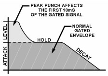 Peak
Punch is a dynamic feature which accelerates the leading edge as the
gated signal opens, adding up to 12dB of gain for approximately 10mS
with proprietary release characteristics. For percussive material such
as drums, fast synthesised sounds or percussive
guitar, the Peak Punch mode of operation will give the most
dramatic results. Peak
Punch is a dynamic feature which accelerates the leading edge as the
gated signal opens, adding up to 12dB of gain for approximately 10mS
with proprietary release characteristics. For percussive material such
as drums, fast synthesised sounds or percussive
guitar, the Peak Punch mode of operation will give the most
dramatic results.
Care
must be taken with material which has a slow attack (especially low
frequency bass sounds), as the Peak Punch may produce transient clicks
at the beginning of sounds, unless the attack knob is also slowed.
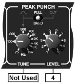 |
Full
Band: The filter section (TUNE) is not used in FULL BAND
mode.
Set the peak punch LEVEL for added attack. Up to 12dB is
available. |
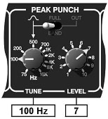 |
Frequency
Band (Low): Using the filter to TUNE the punch. Low
pitch frequencies add depth. |
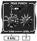 |
Frequency
Band (High): High
punch frequencies could give a 'rim shot' effect on a snare
drum. |
Gating
The unit should be connected in-line with the signal to be
processed via suitable insert points. Ensure, where possible, that the
insert send and return level on your console approximately matches the
operating level of the DS501.
For mono use, each channel may be considered as being completely
independent and set up accordingly. For use with stereo signals, both
channels may be linked; the envelope setting up is then done using the
left hand channel's controls.
Initially, the L.F filter should be set fully anti-clockwise while the
H.F. filter should be set fully clockwise. This will allow the full
audio spectrum of the input programme to be monitored by the side-chain
control circuitry. Set the Range control fully anti-clockwise and the
output selector switch to Normal.
With the Decay control set at its mid-way position, and with suitable
programme material fed into the DS501, increase the Threshold level from
its anti-clockwise position until the gate starts to operate. This will
be indicated by the activity of the traffic light LEDs and you should
also hear the effect on the output signal, in that pauses in the
programme will now be silent. If the Threshold setting is too high, the
gate will start to cut out wanted pieces of programme so you should
adjust it to as low a setting as possible consistent with the effective
removal of low level noise. If the ends of sounds are obviously being
truncated, then a longer Decay time may help. On the other hand, if
unwanted noise is audible after the wanted sound has ended, a shorter
Decay time may well be more appropriate.
There are circumstances when the programme material is corrupted not
only by unwanted random noise, but by some other sound. For example, in
a multi-miked drum kit setup, some hi-hat will inevitably leak into the
snare microphone, some snare drum into the kick drum microphone and so
on. Equally, when recording on location, you may experience problems due
to wind or traffic noise or close-by conversation. If the unwanted noise
is different in pitch to the wanted sound, it is often possible, by
using the Key Listen facility, to use the filters to 'tune' in to the
wanted sound while excluding as much of the unwanted sound as possible.
Used carefully, these filters can significantly increase the gate's
immunity to false triggering.
The Attack control on the DS501 has a very wide range; at its fastest,
it can open almost instantaneously. Conversely, with signals having a
naturally slow or moderate attack, setting the gate attack time too fast
can cause clicks, particularly if the threshold has to be set high
because of excessive background noise. This is one of the most common
anomalies with noise gates, especially when the audio signal being
processed is in the lower frequencies (eg bass guitar, bass drum). With
a high threshold, a low frequency sine wave will be ignored as the
signal starts from its zero level point, as this wave climbs towards its
peak, the level will suddenly exceed the threshold setting, at this
point a very fast attack rate will switch the signal through the noise
gate with such a steep (almost vertical) leading edge that the low
frequency sound will have a single high frequency square wave added to
its first cycle, in other words a 'click' will be heard. In cases like
these, start with a fast attack time and moderate threshold, then
gradually lengthen the attack time until the audible click just
disappears when the gate opens, unless the 'click' is being added as an
effect!
Once the gate envelope has been triggered, The attack cycle will
continue to completion, even if the incoming trigger source is very
short. This can be used to good creative effect by setting a long attack
time, and then processing a crash cymbal or percussive sound, the
resulting slow-attack envelope will completely change the character of
the sound making it appear reversed or 'bowed'.
Ducking
Probably the most common form of Ducking is that used by
radio announcers, whereby the volume of the music being played is
dropped, enabling them to speak over it. In Duck mode the DS501 can
simulate this effect; the music signal is routed to the input and an
amplified version of the announcer's microphone signal is fed into the
Key Input ( 'Ext/Int' switch should be set to 'External'.) The Stereo
Link switch allows a stereo music track to be ducked.
The Range control is used to set the level to which the music will drop
when the ducker is triggered from the Key Input, and the envelope
controls determine the rate at which the level will drop and then
recover. It is usual to select a fairly fast Attack time ( so that the
music level drops rapidly as soon as the announcer begins to speak),
with a slow Release time of a second or so - this will bring the music
level back up slowly and smoothly, and is hence less disconcerting to
the listener. This same technique can be used to reduce the level of
other instruments during a solo.
top of page
APPLICATIONS
LINKED OPERATION
It is important to note that when both channels are linked, the control
signal is derived entirely from the left-hand channel and not from a mix
of the individual channels. This means that stereo signals where one
channel differs significantly from another may fare better if the
channels are not linked.
On the other hand, this mode of linking is very powerful in
synchronising the start and finish of sounds, a typical application
being to tighten up backing vocals. If one singer tends to finish notes
on time while the others hang on too long, the correct version can be
used as the master to ensure that all the others finish at the same
time. Similarly, one sound can be used to gate another without having to
resort to patching in an external key signal. An example might be to
gate a low frequency tone from a bass drum signal and then add this
gated tone to the drum sound to add depth.
By setting up one channel as a gate and the other as a ducker whilst in
stereo link mode, the envelope controls can be used to create some
interesting triggered panning effects, simply by feeding the same signal
into both channels and setting both 'Range' controls to maximum
attenuation.
DIFFICULT MATERIAL
As with any other gate, noise can only be removed during pauses in the
wanted material. If the noise contamination is serious enough to be
evident even during moderately loud programme material, then simple
gating will do little to help. Indeed, the very fact that the gate
produces near-perfect silence during pauses can make the noise content
of the programme material even more apparent. In extreme cases reducing
the range of the Gate to about -15dB will adequately reduce the noise
during pauses but not sufficiently to cause an unacceptably dramatic
change in noise level as the gate opens and closes.
More sophisticated processors such as the Drawmer DF320 are better able
to cope with excessive noise as they adaptively filter the programme so
as to mask the noise during low level passages or where there is little
high frequency content present to mask it. However, the key filters in
the DS501 may also be used to good effect, particularly in situations
where the wanted signal does not occupy the full audio spectrum.
Taking the example of the electric guitar, this produces little below
100Hz or above 3kHz so setting one channel of the DS501 to Key Listen
mode will enable you to use the filters to exclude much of the amplifier
hum at the low end and hiss at the top end while having little effect on
the sound of the guitar. Surprisingly, the same is true of the acoustic
guitar; (even a bright-sounding steel-strung model), and the filters can
be used to reduce the effect of string squeak or the player's breathing.
Other applications of the filter section include shaping direct injected
(DI'd) electric guitar sounds to remove unpleasant overtones and to
simultaneously clean and warm up digital synthesizer sounds. While we
should always endeavour to get the highest quality of programme material
at source, every engineer is occasionally confronted with inferior
material from sources beyond his control. Conventional equalisers seldom
have a sharp enough response to duplicate the function of the Key
filters which invariably results in the wanted material being filtered
as well as the unwanted noise.
Once a signal has been filtered in this way, it may then be processed by
the other channel of the DS501 to apply conventional gating.
DUCKING
In addition to voice over applications, the Duck function of the DS501
may also be used to treat a signal where the peaks are too loud and
require attenuating. In this application, 'Duck' and 'Int' modes should
be selected, and the 'Range' control adjusted to give the desired
attenuation to signals above the 'Threshold' setting. In extreme cases,
the ducking action may be used to remove signal peaks altogether, and by
careful use of the filters, it may be possible to remove a snare drum
from a drum mix or clicks and pops from a recording.
top of page
DS501
TECHNICAL SPECIFICATIONS
INPUT IMPEDANCE 20K Ohms
MAXIMUM INPUT LEVEL +17dB
OUTPUT IMPEDANCE 50 Ohms (bal) 100 Ohms (unbal)
MAXIMUM OUTPUT LEVEL +17dB
BANDWIDTH 23Hz to 31KHz -1dB
NOISE AT UNITY GAIN ref 0dB, GATE open
Wideband 22Hz -
22KHz CCIR
ARM IEC
A Q-Pk CCIR
AV
-90dB
-95dB
-95dB
-97dB -84dB
RMS
-88dB
-93dB
-93dB
-95dB
-
DISTORTION
100Hz
1KHz
10KHz
0dB input <
0.025%
< 0.025%
<0.025%
POWER REQUIREMENTS 93-125Volt or 185-250Volt at 50-60Hz, 9 Watts
FUSE RATING 32mA for 230Volt, 63mA for 115Volt
FUSE TYPE 20mm x 5mm, Class 3 Time delay, 250 Volt working.
CONFORMING TO BS EN 60127-2:1991 SHEET III
CASE SIZE 482mm (w) x 44mm (h) x 200mm (d)
WEIGHT (incl packaging) 3.4 Kgs |